


Image
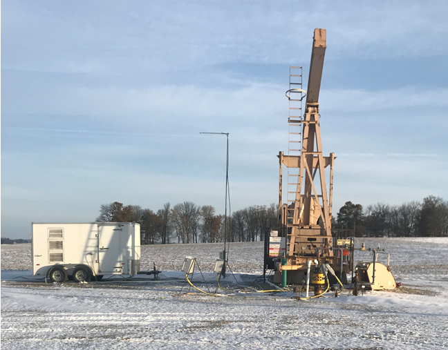
Field Demonstration:
Trial Performed on Liquid Loaded, Unconventional Shale Gas Well in Indiana
Increase gas production and recoverable reserves from a liquid loaded, unconventional shale well with a horizontal wellbore.
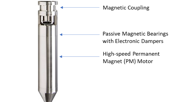
Deploy the first full-scale commercial Subsurface Compressor System™ to:
The trial resulted in a 62% increase in clean natural gas production and a 50% increase in liquid production over its steady-state performance with a rod pump prior to the SCS installation.
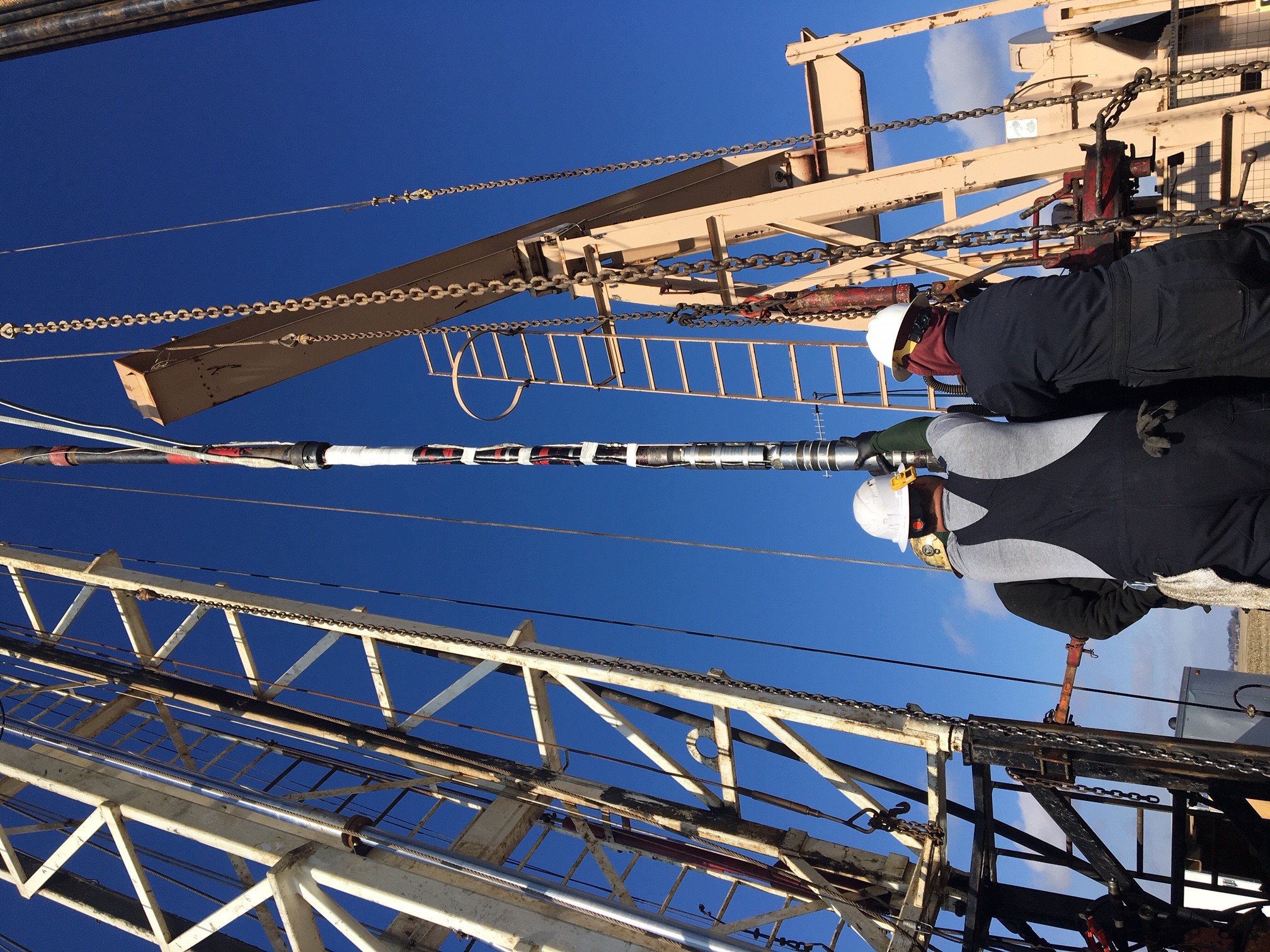
This was the first time certain topside and subsea technologies were deployed downhole:
The wellsite was equipped with a topside high frequency drive, necessary transformers, communication and safety systems located in mobile control center operate the SCS motor without sensors.
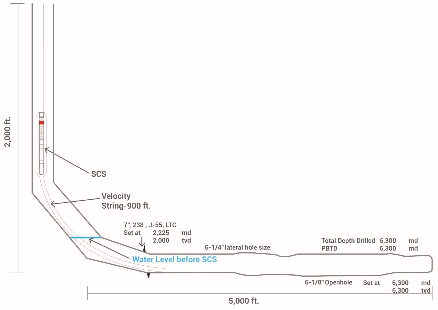
The well is relatively shallow with a vertical depth of 2,000 ft., and has a long horizontal section of 5,000 ft., where liquid had accumulated.
Prior to installing the compressor
The well's gas production was about 185 MSCFD and its liquid production (via rod pump) was 5-7 BPD. Without the rod pump, the well choked in a few hours.
With the SCS
The well stabilized at a gas production of 300 MSCFD (+62%) with the help of nitrogen injection to kick off the well over a two-day period, and the liquid production increased by over 9 BPD (+50%) over the same period. The nitrogen injection helped push the liquids within the vertical and horizontal wellbore into the formation and enabled to SCS to startup without being submerged in kill fluid. The trial period started at the end of October, and the SCS was pulled in early December.
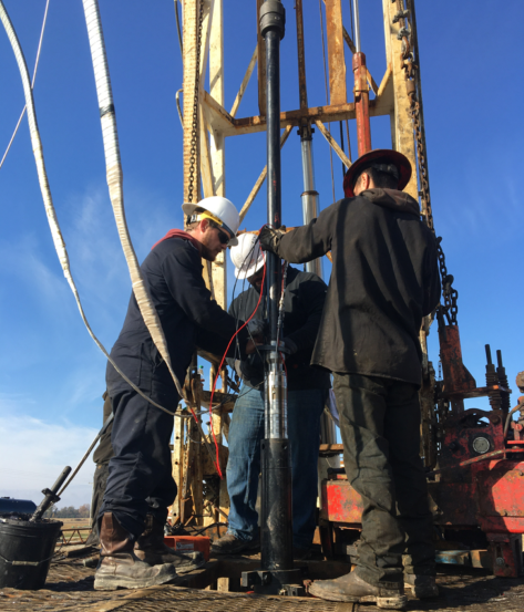
Operation
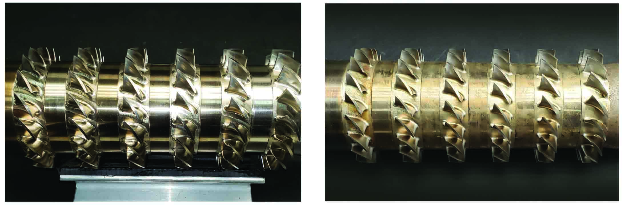
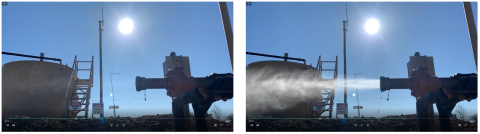
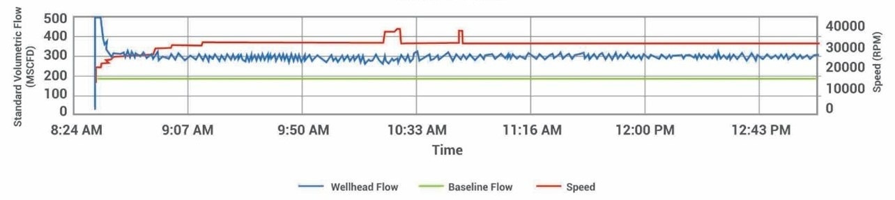
The Turner et al (1969) correlation assumes that free flowing liquid in the wellbore forms droplets suspended in the gas stream with gravity force pulling the droplets down and the drag force pushing the droplets upward. The minimum required gas velocity to lift liquids to the surface was 22 ft/s. While the SCS operated at 20,000 RPM, the gas velocity within the vertical wellbore was 22.5 ft/s, and the well operated in the transitional state between the slug and annular-mist flow conditions. The liquid production at the surface during that time was detectable although intermittent. When the SCS operated at 30,000 RPM, the gas velocity increased to 29 ft/s, and a high rate of liquid was carried to the surface. As shown in the picture below, the hybrid axial compressor was able to atomize the liquid into a very fine mist, which together with the increased velocity and heat generated from the exit of the compressor helped carry the liquids to the surface.
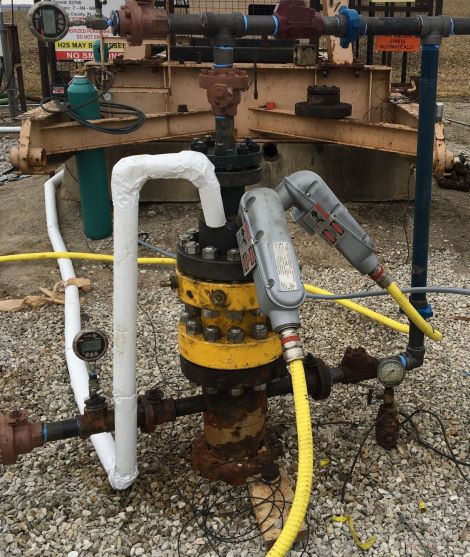
Flow and Speed
Liquid Production at 20,000 and 30,000 RPM
The hybrid compressor, which had 6 stages of Inconel rotating blades, showed no sign of wear or impingement due to the liquids. The design point pressure ratio of the compressor at 30,000 RPM was 1.25, and this was validated by the downhole memory gauges that were placed at the suction and discharge of the compressor.